Ultra-Met Pipe® CHROMIUM CARBIDE OVERLAY PIPE
Ultra-Met Pipe®
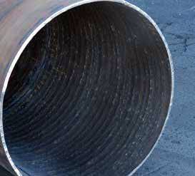
Ultra-Met Pipe is a superior abrasion resistant piping solution for extreme applications. The Ultra-Met pipe product line was designed to combat severe abrasive wear with moderate to low impact over a wide temperature range.
Ultra-Met Pipe is a fabricated pipe produced, using out industry proven, high quality chrome carbide overlay plate Ultra-Met to offer outstanding abrasion resistance for most low pressure applications. Ultra-Met Pipe has reduced downtime in the steel, cement, paper, mining, power generation, aggregate, cullet and glass industries. Ultra-Met Pipe is the preferred choice in the transportation of materials such as; aggregates, ash, coal, gravel, limestone, magnetite, mil scale, mine tailings, ores, pyrites, raw kiln feed, slurries, sludge, slag and sand.
Ultra-Met piping products having all the advantages, but without the disadvantages of the double wall or cast lined pipes.
Advantages
- Reduces life cycle maintenance cost, & unplanned outages
- Superior wear resistance under severe conditions
- Abrasion resistant properties up to 1,250°F.
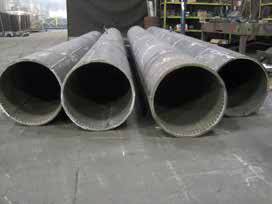
- Wide variety of pipe sizes for most applications
- Available in straights, mitered bends, wyes, tees & reducers
- Outlasts mild steel pipe by up to 10 times
- Outlast Basalt in moderate impact applications
- Easily installed & field patched
Sizing
(Not NPS standard wall thickness) (for reference only)
There are multiple wall thickness options. Ultra-Met pipe is designed to match the ID of standard schedule low carbon pipe. Coupling options for Ultra –Met pipe are designed to mate to standard size pipe configurations.
| 3/8″ nom. wall (1/8″ SOL on 1/4″ base) | 1/2″ nom. wall (1/4″ SOL on 1/4″ base) | 3/4″ nom. wall (1/4″ SOL on 1/2″ base) |
|||||
|---|---|---|---|---|---|---|---|
| Diameter (O.D.) | NPS O.D. | O.D. | lbs/ft | O.D. | lbs/ft | O.D. | lbs/ft |
| 8 | 8.6 | 8.7 | 35.0 | — | — | — | — |
| 10 | 10.7 | 10.8 | 43.2 | 11.0 | 58.9 | — | — |
| 12 | 12.7 | 12.8 | 51.1 | 13.0 | 69.5 | 13.5 | 108.3 |
| 14 | 14.0 | 14.0 | 56.2 | 14.3 | 76.2 | 14.8 | 118.3 |
| 16 | 16.0 | 16.0 | 64.2 | 16.3 | 86.9 | 16.8 | 134.3 |
| 18 | 18.0 | 18.0 | 72.2 | 18.3 | 97.6 | 18.8 | 150.4 |
| 20 | 20.0 | 20.0 | 80.2 | 20.3 | 108.3 | 20.8 | 166.4 |
| 22 | 22.0 | 22.0 | 88.2 | 22.3 | 118.9 | 22.8 | 182.4 |
| 24 | 24.0 | 24.0 | 96.3 | 24.3 | 129.6 | 24.8 | 198.5 |
| 26 | 26.0 | 26.0 | 104.3 | 26.3 | 140.3 | 26.8 | 214.5 |
| 28 | 28.0 | 28.0 | 112.3 | 28.3 | 151.0 | 28.8 | 230.5 |
| 30 | 30.0 | 30.0 | 120.3 | 30.3 | 161.7 | 30.8 | 246.6 |
| 32 | 32.0 | 32.0 | 128.3 | 32.3 | 172.4 | 32.8 | 262.6 |
| 34 | 34.0 | 34.0 | 136.4 | 34.3 | 183.1 | 34.8 | 278.7 |
| 36 | 36.0 | 36.0 | 144.4 | 36.3 | 193.8 | 36.8 | 294.7 |
Comparison
Based on Mild Steel
| Mild Steel | Ultra-Met Overlay Pipe |
|
|---|---|---|
| Hardness | 120-150 BHN | 56- 62 Rc |
| Max Temperature | 750° F (400° C) | 1250° F (676° C) |
| Abrasion Resistant | Poor | Very Good |
| Impact Resistant | Good | Good |
| Std. Sizes (OD) | Unlimited | 8″ to 40″ |
| Handling/Installation | Excellent | Very Good |
| Fabrication | Unlimited | Some Limitations |
| Emergency Repair | Easily Patched | Easily Patched |
| Initial Cost | 1 | 6-8x |
| Life Expectancy | 1 | Up to 10x |
Mechanical Properties
| Layers | Surface Hardness | ASTM G-65 Mass Loss | Carbide Hardness (Max.) |
|---|---|---|---|
| Single | 56 - 62 Rc | .195 - .235 g | 1750 HV |
| Double | 56 - 62 Rc | .189 - .208 g | 1750 HV |
FABRICATION
We recommend the use of St. Lawrence’s fabrication services to eliminate processing and fabrication errors.
End Options/Coupling Methods
We offer a wide range of options including:
Field Fabrication/Modification of Pipe
All St. Lawrence’s pipe products must be supported on both sides of the cut area to prevent damage to the pipe and or cutting equipment. Normal safety and workmanship practices are recommended.
WARNING: All structural welding must be confined to the base plate and not overlap into the overlay. This procedure will prevent carbon embrittlement and failure of the weld.
Cutting
Ultra-Met can be cut with water jet, plasma burning equipment, air arc or abrasive saws. When cutting with an abrasive saw, the use of an abrasive silicon carbide wheel is recommended.
Joint Preparation
Inspect surfaces to be welded – avoid welding areas that have tears, cracks and other discontinuities. Clean joint area at least 1/2″ from weld joint; remove all loose scale, rust, moisture, grease, etc. Position parts into as close contact as practical; root opening should not exceed 3/16″. For separations greater than 1/16″, increase leg of fillet weld by the amount of the opening.
WELDING
Place welds on exterior of pipe first. Working from the exterior of the pipe, join the pipes using any low carbon electrode is acceptable. (AWS 5.1 – E7018 or 7016 type), 1/8″ or smaller. Maintain a maximum of 1/4″ weld fillet per pass. Rotate the pipe during the welding process to eliminate excessive starting and stopping of weld. Allow pipe to cool before applying additional exterior beads. After the structural welds are complete, fill the joint on the pipe interior with St. Lawrence PN 200-W-ACF hard surface wire. Grind the interior surface smooth. Additional cracks may be noticeable on the inside surface of the pipe, but these will not affect the abrasion resistance.
End Options/Coupling Methods
We offer a wide range of options including:
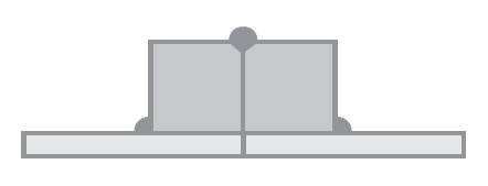
Standard Weld Rings
- Typically no face seal weld.
- Most common style.
- Butt weld field applied.
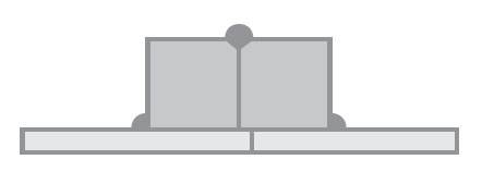
Self-Aligning Weld Rings
- Male/Female recess.
- Butt weld field applied.

Victaulic End Styles
- Fast installation
- Low working pressure
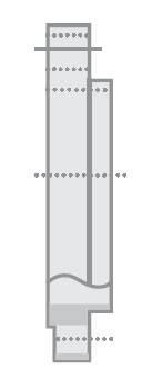
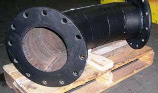
Standard Flanges
- 150#, 300# or 600# most common: others available.
- Industry standard dimensions.
- Raised face (shown) & plate flanges.