


Custom Engineered Wear Resistant Solutions
SLS Bimetallic Wear Parts combine a number of metallurgical properties into one unique wear resistant material which today has been widely used in most abrasive wear applications.
Bimetallic Wear Parts are produced by metallurgically bonding a (cast) highly alloyed chromium molybdenum white iron to a mild steel backing plate. The bonding process yields a high shear strength wear solution. The hardness (700 BHN) of the alloy provides maximum abrasion resistance, while the steel backing plate acts as a means of absorbing high impacts and allows easy fitting and use.
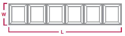
| Approx. Size (L x W) | Thickness (H) | ||||
|---|---|---|---|---|---|
| Part Number | mm | in. | mm | in. | Weight |
| SLS CB25 | 240 x 25 | 9 7/16″ x 1″ | 25 | 1″ | 2.4 lb |
| SLS CB40 | 240 x 40 | 9 7/16″ x 1 1/2″ | 25 | 1″ | 3.7 lb |
| SLS CB50 | 240 x 50 | 9 7/16″ x 2″ | 25 | 1″ | 4.8 lb |
| SLS CB65 | 240 x 65 | 9 7/16″ x 2 1/2″ | 25 | 1″ | 6.2 lb |
| SLS CB90 | 240 x 90 | 9 7/16″ x 3 1/2″ | 25 | 1″ | 9.2 lb |
| SLS CB100 | 240 x 100 | 9 7/16″ x 4″ | 25 | 1″ | 9.7 lb |
| SLS CB130 | 240 x 130 | 9 7/16″ x 5 1/8″ | 25 | 1″ | 12.3 lb |
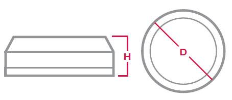
| Part Number | Diameter (D) | Base Thickness | Total Thickness (H) | Weight |
|---|---|---|---|---|
| SLS WB60 | 2 3/8″ | 7/16″ | 1 3/16″ | 1.5 lb |
| SLS WB75 | 3″ | 7/16″ | 1 3/16″ | 2.2 lb |
| SLS WB90 | 3 1/2″ | 7/16″ | 1 3/16″ | 3.3 lb |
| SLS WB115 | 4 1/2″ | 1/2″ | 1 1/4″ | 5.7 lb |
| SLS WB150 | 6″ | 5/8″ | 1 5/8″ | 12.5 lb |
1) Clean the surface that block will be welded to.
2) For outside curves: Tack weld one end of the bar to surface in at least three places using a minimum of 1/2″ of weld in each deposit (shown below). Hammer down unwelded end of the bar to form the bar to the curved surface. Stitch weld until bar is firmly in place.
3) For inside curves: Tack weld one end of the bar to surface using a minimum of 1/2″ of weld in each deposit (shown below). Starting from the center, hammer down the bar to form the bar to the curved surface. Stitch weld until bar is firmly in place.
1) Ensure the surface that the wear block is to be welded to is as clea n and flat as possible.
2) Tack weld the wear blocks into position.
3) Stitch weld in 2″ length runs, alternating ends or similiar to minimize heat imput. Do not deposit weld within 1/8″ from the bond zone between the white iron and mild steel backing plate.
1) Clamp bar down securely.
2) Cut through base to white iron bond area.
3) Wrap bar with a cloth and carefully hit it with a hammer. Bar should break cleanly at the notch.