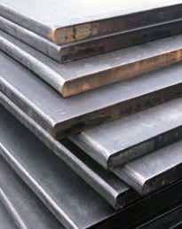
AR-MAX® NICKEL ALLOY ARMOR PLATE
AR-MAX®
AR-MAX is designed for applications where both abrasion and impact resistance are major considerations. You can expect a significantly longer service life when critical wear parts are fabricated from AR-MAX alloy steel plate. Alloy-rich chemistry with low sulfur and typical hardness of 444-532 BHN give AR-MAX excellent strength and toughness.
AR-MAX is produced to rigid specifications, vacuum degassed, quenched and tempered into a unique high strength alloy steel made for a combination of ultra high strength and toughness
Advantages
- Abrasion Resistant
- Quenched & Tempered
- Extends Service Life
- Complete Through Hardness
- Impact Resistant
- Formable
- Excellent Cold Weather Properties
- Welds Easily

Available Stock Sizes
width x length in inches
| Thickness | Width | Lengths |
|---|---|---|
| 1/4″ to 3″ | 48″ to 96″ | up to 288″ |
These sizes are available for immediate shipment. All 240″ and 288″ stock is available in 120″ and 144″ lengths at no extra cost. Strips cut to your requirement. Rectangles, squares, circles and irregular shapes can be flame cut to your specifications. Tolerances for thickness, width and length per ASTM A6 Tables 1 and 8.
Chemistry (typical %)
Manufactured in Compliance with ISO 9002 ABS-QE
Steel Plate Comparison
| Product | Abrasion Resistance | Impact Resistance | Weldability | Machinability | Forming | Cutting |
|---|---|---|---|---|---|---|
| MAN-CRO 400F | G | VG | VG | F | G | VG |
| MAN-CRO 450F | G - VG | G | G | M - F | F - G | G - VG |
| MAN-CRO 500F | VG | F | F | M | F | G |
| AR-Max | VG | VG | VG | F | G | VG |
| Ultra-Met Standard | E | G | E(1) | M(2) | F | G(4) |
| Ultra-Met Impact | VG | G - VG | E(1) | M(2) | M - F | G(4) |
| Ultra-Met Abrasion | E - S | G | E(1) | M(2) | F | G(4) |
| Hardlite | E | G | E(1) | M(2) | F | G(4) |
| SLS 14% Manganese | F | E | VG(3) | M | G | G |
S: Superior, E: Excellent, VG: Very Good, G: Good, F: Fair, M: Marginal
(1) Carbon Base Only
(2) EDM, Plasma or Air Arc holes only
(3) When welding Manganese to any other metal, use 309 or 310 SS electrode w/ minimum heat input
(4) Plasma, waterjet or laser
Mechanical Properties (typical)
(1″AR-MAX Oil Quenched 1750° F)
| Temp | Yield PSI | Tensile PSI | Elong 2″, % | Red. Area % | Hardness BHN |
|---|---|---|---|---|---|
| Quenched | 193000 | 251000 | 11.5 | 39 | 470 |
| 400 | 188000 | 239000 | 12.2 | 41 | 444 |
| 600 | 181000 | 225000 | 11.8 | 37 | 425 |
| 800 | 162000 | 198000 | 13.0 | 43 | 389 |
| 1000 | 151000 | 169000 | 17.5 | 51 | 351 |
| 1200 | 115000 | 139000 | 19.0 | 57 | 277 |
Charpy Impact Properties (typical)
(Ft. Lbs.) (Longitudinal)
| Thickness | Hardness BHN Typical | 72° F | 0° F | -50° F |
|---|---|---|---|---|
| 3/4″ | 444 | 43.1 | 32.5 | 28.2 |
| 1″ | 425 | 39.0 | 29.0 | 27.0 |
| 1-1/2″ | 401 | 36.7 | 23.7 | 18.0 |
FABRICATION
We recommend the use of St. Lawrence’s fabrication services to eliminate processing and fabrication errors.
Cutting
Conventional gas cutting procedures are satisfactory. Some hardening along the cut edge may occur. Pre-heating the plate to 300° F – 350° F before flame cutting can decrease stresses. Plasma is recommended. In addition, the use of a heat blanket is recommended to slow the cooling rate.
Forming
AR-MAX has been bend tested using 6″ dia. pin. 1/2″ through 1″ thick coupons were used for both longitudinal and transverse tests.
| Thickness | Bend Radius |
|---|---|
| Up to 1/2″ | 6t |
| Over 1/2″ up to 1″ | 3t |
If the bend radius is transverse to rolling direction of plate, radii should be increased. “Bumping” in a press brake is the r ecommended procedure for forming heavier sections. Care should be exercised to insure that brake equipment has capacity to bend form hardened steels, usually 4x power required to form mild steel. Some representative values on actual cold bending are shown below.
| Thickness | Min. Radius |
|---|---|
| 1/4″ | 6″ |
| 1/2″ | 12″ |
| 3/4″ | 18″ |
| 1″ | 24″ |
| 1¹/₄″ | 30″ |
Preheating*
| Thickness | ||
|---|---|---|
| up to .5″ | .5″-2″ | 2+″ |
| 250°F | 300°F | 350°F |
*post weld heat treating recommended to slow cooling rate
Machining
Standard high speed drill bits may be used on ARMAX at full hardness with some modifications.
A) Included angle should be approximately 140°.
B) Grind lip to a 5° positive rake with a .031″ land width.
C) To reduce pressure and work hardening, reduce web to approximately .09″.
D) Cutting speeds of 4-6 SFM and feeds of .004″- .005″ per revolution are recommended for standard high speed drills.
E) With cobalt or similar grades of high speed drills, cutting speeds of 8-10 SFM should be used.
F) Positive power feed is essential to provide a continuous chip and minimize work hardening.
G) For countersinking, use same feed and speed as for drilling. Four or six-flute tool recommended.
WELDING
Consumables:
AWS E7018 is usually acceptable as an all purpose rod to join AR-MAX® to itself or to most low alloy steels. An AR-MAX® weldment will produce desired dilution with the electrode to enhance greater strength at the weld joint.
AWS E8018, E9018, E11018, E12018 all are examples of low hydrogen electrodes which may be used to weld AR-MAX®. To further enhance strength at weld joint, E11018-M can be applied.
AWS E309 or E310 are recommended when joining AR-MAX® with either 11- 14% austenitic manganese or stainless steels.
CAUTION
Do not use an oxyacetylene torch for gouging since the heat input by this method is difficult to control and excessive heat input may result in a detrimental reduction of mechanical properties of the base metal near the weld joint.
